> For the complete documentation index, see [llms.txt](https://tacsdr-docs.allseeingtech.ca/llms.txt). Markdown versions of documentation pages are available by appending `.md` to page URLs; this page is available as [Markdown](https://tacsdr-docs.allseeingtech.ca/readme.md).

# Operator Manual

This manual helps operators complete basic TACSDR setup, including unboxing, power-on, accessory connection, status checks, and radio operations using factory pre-programmed modes.

{% hint style="success" icon="message-exclamation" %}
This manual is for basic operation. For custom programming, radio-frequency changes, custom-application installs, integrating third-party accessories, or advanced setup, use the [Developer Manual](https://tacsdr-docs.allseeingtech.ca/developer-manual/).
{% endhint %}

<div data-with-frame="true"><figure><img src="/files/I3MkmE02IOLcg3ss1W12" alt=""><figcaption></figcaption></figure></div>

***

## What is TACSDR?

<mark style="color:$success;">**TACSDR**</mark> is a <mark style="color:$success;">**TAC**</mark>**tical&#x20;**<mark style="color:$success;">**S**</mark>**oftware-**<mark style="color:$success;">**D**</mark>**efined&#x20;**<mark style="color:$success;">**R**</mark>**adio** built for the modern electromagnetic environment. It combines flexible radio-frequency transmission and reception capabilities, command and control integrations, rugged field-ready operation, and an easy-to-use interface in one compact system.\
\
TACSDR is a handheld radio built for flexibility. Out-of-the box it comes with 2 pre-programmed modes for voice and data communications, however, with a developer license, operators can add custom RF and application specific operations to TACSDR.

<table data-card-size="large" data-view="cards"><thead><tr><th></th><th></th><th data-hidden data-card-cover data-type="image">Cover image</th></tr></thead><tbody><tr><td><h4><strong>Need for Tactical Connectivity</strong></h4></td><td>Modern tactical missions depend on sensors, software, data links, and real-time situational awareness, creating a need for radios that deliver fast, mobile communications in changing field environments. TACSDR rises to meet this mission need!</td><td><a href="/files/Ucf4Aui2sDtwH3r7df2H">/files/Ucf4Aui2sDtwH3r7df2H</a></td></tr><tr><td><h4><strong>Need for Adaptable RF Systems</strong></h4></td><td>Evolving frequency, network, and data requirements demand adaptable RF systems, creating a need for flexible radios that can be upgraded, reconfigured, and tailored to different field mission profiles quickly. TACSDR provides a rugged, reconfigurable radio platform that adapts to changing mission needs without hardware redesign.</td><td><a href="/files/g2bG4PkSBxbCZPieUUtU">/files/g2bG4PkSBxbCZPieUUtU</a></td></tr></tbody></table>

With TACSDR, operators can power on, choose pre-programmed and custom-specific RF[^1] modes for communications and sensing, connect a wide range of external accessories, and start operating radio systems quickly without deep RF knowledge.

TACSDR's architecture is centered around flexibility. It houses a user-programable CPU[^2] connected to [AllSeeing's proprietary Software-Defined Radio](https://www.allseeingtech.ca/). Operators can use TACSDR through its touchscreen interface, while developers can program the radio through simple interfaces connected to a main laptop or desktop.

<details>

<summary>More on TACSDR System Architecture</summary>

<div data-with-frame="true"><figure><img src="/files/d0746MnEMb5aSVojSxpW" alt=""><figcaption></figcaption></figure></div>

The diagram above is a simplified block-level representation of TACSDR. It is intended to help operators understand the relationship between TACSDR's hardware components. By understanding the block architecture, operators can know what is possible with TACSDR. Each block is summarized below.

* **Central processing unit:** TACSDR's main computer. It runs the interface, modes, radio control, GNSS, audio/data routing, and module coordination.
* **AllSeeing software defined radio:** TACSDR's main RF engine. It handles transmit and receive processing, and supports programmable waveforms, modes, and signal processing. The RF specefications can be found in the [specefications page](https://tacsdr-docs.allseeingtech.ca/spec/).
* **RF amplifier subsystem:** Supports the RF transmit and receive path to the **RX/TX antenna connector**. It exchanges RF data with the SDR and control signals with the processor. The RF specefications can be found in the [specefications page](https://tacsdr-docs.allseeingtech.ca/spec/).
* **GNSS unit:** Provides GNSS position and timing data through the **GNSS antenna connector**. PPS can help synchronize system timing when a GNSS fix is available.
* **Display controller and interface:** Connects the touch screen to the processor for status, mode selection, settings, and monitoring.
* **ODU audio/data connector:** External port for supported audio and data accessories. Align the connector carefully and do not force it.
* **36-pin expansion port:** Adds support for approved accessories and custom interfaces such as USB and Ethernet.
* **Wi-Fi and Bluetooth:** Support configuration or accessories, depending on the selected mode and settings.
* **Power subsystem:** Distributes power from the **swappable batteries** and supports charging through the **DB9 charger connector**. The processor also uses it for power control and safe startup.

</details>

{% hint style="success" icon="message-exclamation" %}
Use the [TACSDR specification page](https://tacsdr-docs.allseeingtech.ca/spec/) for full hardware and performance details. The specification page shows the exact technical numerical data for system integration, troubleshooting, or mission planning.
{% endhint %}

### TACSDR Exterior Overview

**The figure below** shows the main external features of TACSDR.

The front has a touchscreen for selecting modes, checking status, and changing settings. The top has the power button, RF antenna connectors, the GNSS antenna port, and the main accessory connection for the headset and PTT. The side has expansion ports and the back has a battery bay. The bottom area has the charging port. Its rugged body, protected screen, and easy-to-reach connectors make TACSDR easy to carry, connect, power, and use in the field.

<figure><img src="/files/MlkSkVKOwuzEWu4cGZMa" alt=""><figcaption></figcaption></figure>

<details>

<summary>More on TACSDR's Exterior</summary>

### TACSDR Exterior Physical Overview

TACSDR is designed as a compact handheld radio module for field operation. Its approximate size is **160 mm tall, 80 mm wide, and 50 mm deep**, with an operating weight of approximately **700 g including batteries**. The enclosure is sized for portable use while still providing enough space for protected connectors, a recessed display, removable power, and expansion access.

#### Front Face

<div data-with-frame="true"><figure><img src="/files/lt6VAno66Ij9CLfg92dV" alt=""><figcaption></figcaption></figure></div>

The front face is the primary operator interface area. The touchscreen is protected by the surrounding enclosure and is used during setup, mode selection, status review, and radio configuration. Operators should keep the screen clean and avoid using sharp objects on the display surface. The identification label below the screen provides product and serial information for maintenance, inventory, and support.

#### Top Interface Panel

<div data-with-frame="true"><figure><img src="/files/hHZrjpdXU8iv8aSqO4k8" alt=""><figcaption></figcaption></figure></div>

The top panel groups the main field-access connectors in one location so antennas, accessories, and operator controls can be reached quickly. This area includes the power button, RF antenna connections, GNSS antenna connection, and the main accessory interface for headset and push-to-talk operation. Before use, operators should check that antennas and accessories are properly seated and that unused connectors are protected when possible.

#### Side Expansion Ports

<div data-with-frame="true"><figure><img src="/files/qMxvz81VMQ1hTeUJNJsU" alt=""><figcaption></figcaption></figure></div>

The side expansion area is intended for approved accessories, custom interfaces, or mission-specific hardware. These ports are not normally required for basic operation. Operators should avoid connecting unapproved equipment, and expansion-port use should be limited to trained users or system integrators. The side connector breaks out 36 high speed GPIO lines connected to TACSDR CPU. with various adapters, ethernet, USB, RS422 and other interfaces can be adapted to the side connector.

#### Battery Bay

<figure><img src="/files/IFHNhKDGvKTt2HS9Saqf" alt=""><figcaption></figcaption></figure>

The battery bay houses the removable power source. Before powering on TACSDR, confirm that the battery is installed correctly and fully secured. During field use, inspect the battery area for dirt, moisture, or damage before inserting or removing the battery. Power should be turned off before battery replacement whenever possible.

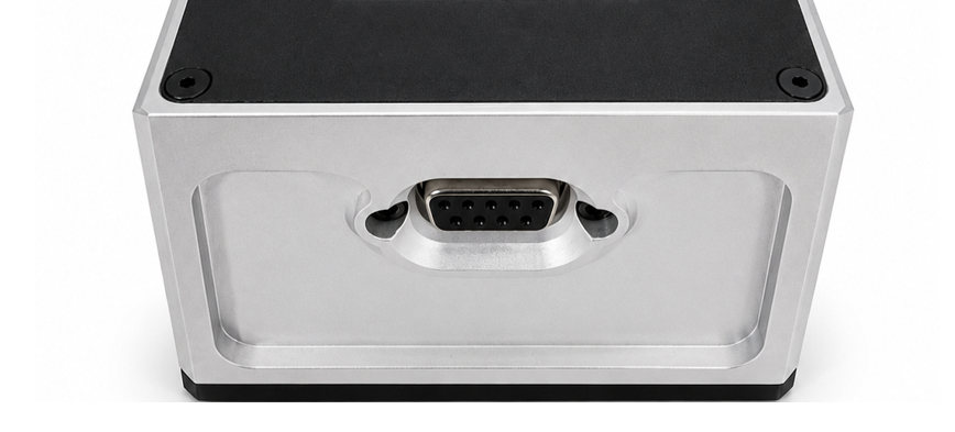
#### Charging Port and external battery port.

<figure><img src="/files/uv3HZPRxZq4E4sBnwmaJ" alt=""><figcaption></figcaption></figure>

The charging port is used to recharge the system with approved charging equipment. Inspect the connector before use and make sure it is clean, dry, and undamaged. Do not force the charger into the port. If the connector does not seat properly, remove it and check alignment before trying again. An external battery module may also be connected to the charging port.

#### Exterior Construction

TACSDR uses a rugged mixed-material enclosure with protected controls, recessed surfaces, and reinforced connector areas. The design helps protect the radio during transport, setup, and field handling while keeping the main controls accessible. Operators should periodically inspect the housing, screws, labels, ports, and connector areas for wear or damage.

</details>

TACSDR can be supplied in different colors and finishes to match customer and mission needs. Color selection can support visual identification, reduced visibility, or program-specific equipment standards.

<figure><img src="/files/R7XZf9wlIkDwuFRb69PX" alt=""><figcaption></figcaption></figure>

Examples may include standard dark finishes for general field use, low-visibility color schemes for tactical environments, or customer-specific exterior treatments that match other deployed equipment.

If appearance or signature control is important for an application, confirm the required color, coating, and finish during purchase from [AllSeeing](https://www.allseeingtech.ca/).

***

## Physical Setup

{% stepper %}
{% step %}

### Unboxing

**TACSDR** ships with the radio and accessories needed for basic setup and use. Open the box carefully. Place all items on a clean, flat surface.

The standard TACSDR kit includes these items:

1. TACSDR handheld radio (X1)
2. 18650 Rechargeable battery cells (X6)
   1. [Hex L-Key drive](https://www.mcmaster.com/7289A111/) (X2) for battery replacement
3. Gooseneck antenna (X1)
4. Active GNSS antenna (X1)
5. Single-bay or 6-bay charging unit (X1)
   1. Charger wall adapter
   2. USB-C to USB-C cable (X1)
   3. USB-C to USB-A cable (X1)
6. Audio headset (X1)
   1. Push-to-talk (PTT) (X1)
   2. Neck-band (X1)
   3. AA batteries (X2) for the headset
7. Radio carrying pouch (X1)
8. Battery carrying pouch (X1)

<figure><img src="/files/pDIO9UtVvHMFuzYiREtu" alt=""><figcaption></figcaption></figure>

Before powering on TACSDR, confirm all parts are present and undamaged. Check the radio, display, antenna connectors, battery pack, charger, and cables for cracks, loose parts, bent pins, [damaged insulation, or shipping damage](#user-content-fn-3)[^3].

Confirm the antenna and battery are included before continuing. <mark style="color:$warning;">Do not operate TACSDR without the correct antenna unless an advanced setup or test procedure requires it.</mark>

Keep the original packaging until basic setup and transmit and receive checks are complete. Operators may need it for storage, transport, or return shipping.

If anything is missing, damaged, or incorrect, stop setup and contact [AllSeeing support](https://www.allseeingtech.ca/).
{% endstep %}

{% step %}

### Connecting accessories

TACSDR can connect to a wide range of accessories and third-party devices such as cameras, sensors, and other equipment through [Wi-Fi](#wi-fi), [Bluetooth](#bluetooth), and [the side connector](#side-connector). However, each TACSDR kit includes a set of **primary accessories** required for basic operation.

This section explains how to connect the **primary accessories** before powering on the device.

<details>

<summary>Gooseneck Antennas</summary>

TACSDR includes a multi-band "gooseneck[^4]" antenna. Power off TACSDR before installing or removing the antenna.

<div data-with-frame="true"><figure><img src="/files/OkeZenKbyPScYJdv55ed" alt=""><figcaption></figcaption></figure></div>

The gooseneck antenna connects to the RF ports. TACSDR has two RF antenna ports:

1. **RF Port L - Left TNC Port**\
   Use **RF Port L** for 5W transmit and receive operation. This port supports RF reception and high-power RF transmission up to **5 W**. **RX and TX can use separate center frequencies on this port.** Connect the antenna here when operating on Channel 0.
2. **RF Port R - Right TNC Port**\
   Use **RF Port R** for transmit and receive operation. This port supports RF reception and low-power RF transmission up to **10 mW**. **RX and TX must use the same center frequency on this port.** Connect the antenna here when operating on Channel 1.

To install the gooseneck antenna, align the connector with the selected TNC port. Tighten it by hand until secure.

Do not force or overtighten the connector. The GNSS antenna connects to the SMA port and provides satellite positioning and timing.

<div data-with-frame="true"><figure><img src="/files/s8Aun4LMb8M2rlVhzzHb" alt=""><figcaption></figcaption></figure></div>

The TACSDR gooseneck antenna has several strong operating regions across the spectrum. The best performance is around the main return-loss dips shown in the image above, especially near **550 MHz**, **940 MHz**, **1400 MHz**, and parts of **1550–1650 MHz**. These areas should give the best RF efficiency and are preferred for transmit/receive operation.

From an operator perspective, this antenna performs best where the **return loss is more negative**. A deeper dip means the antenna is better matched, sends more RF energy out, and reflects less power back into the radio.

For the chart above, operators should treat:

* **Great performance (dark green regions):** below **-10 dB**
* **Usable performance (light green regions):** around **-6 dB to -10 dB**
* **Less desirable:** above **-6 dB**, especially near **-1 to -4 dB**

{% hint style="success" icon="hands-clapping" %}
**Important:** Do not transmit unless the correct antenna is connected to the RF Receive AND Transmit port.
{% endhint %}

</details>

<details>

<summary>GNSS Antenna</summary>

TACSDR includes an active GNSS antenna for satellite positioning and [precision timing](#gnss).

<div data-with-frame="true"><figure><img src="/files/UYCFXSjfDSJD12yWO5VI" alt=""><figcaption></figcaption></figure></div>

{% hint style="success" icon="hands-clapping" %}
It is recommended to power off TACSDR before installing or removing the GNSS antenna.
{% endhint %}

The active GNSS antenna connects to the SMA GNSS antenna port on the top of the TACSDR.

Use the GNSS port only for the supplied or approved active GNSS antenna. The GNSS antenna provides satellite positioning and timing information to TACSDR. It is not used for RF voice or data transmission.

To install the GNSS antenna, align the SMA connector with the GNSS antenna port. Tighten it by hand until secure.

Place the GNSS antenna where it has a clear view of the sky. For best performance, keep the antenna facing upward and away from large metal objects, RF antennas, or other obstructions.

Do not force or overtighten the connector. Do not connect the GNSS antenna to the RF antenna ports.

</details>

<details>

<summary>18650 Batteries</summary>

**NOTE:** TACSDR is normally shipped with the batteries already installed. This section applies only if the batteries need to be installed, replaced, or inspected.

<div data-with-frame="true"><figure><img src="/files/t3WGpuicKQJ4Pg8k6tUC" alt=""><figcaption></figcaption></figure></div>

The battery compartment is on the rear of TACSDR, as shown in the image.

Place the unit face down on a clean, dry surface. Use the supplied [Hex L-Key drive](https://www.mcmaster.com/7289A111/) to loosen the four battery cover screws. Keep the screws in a safe place. Then remove the cover.

The batteries are standard 3.60V lithium-ion rechargeable cells. By default, TACSDR ships with EVE INR18650/33V cells. The data sheet is provided below for reference.

{% file src="/files/rlnu1JOLRysA6oDOHz3X" %}

Insert the batteries one at a time. Make sure each battery sits fully in its slot. <mark style="color:$warning;">The positive terminals must face UP and match the + marking inside the battery compartment.</mark> Do not force the batteries into place.

After installing the batteries, reinstall the cover and tighten the four screws evenly by hand. Do not overtighten.

Before first use, make sure the batteries have enough charge. If the battery level is low, charge the unit before continuing.

</details>

<details>

<summary>Headset</summary>

<div data-with-frame="true"><figure><img src="/files/KnmdKgIIZt0jlFZOSy6M" alt=""><figcaption></figcaption></figure></div>

TACSDR uses a **NATO TP-120 compatible headset** for audio input and output. Connect the headset through the supplied **Push-To-Talk (PTT) interface**. This interface connects the TP-120 headset to the TACSDR **ODU® connector**.

To connect the headset, plug the TP-120 connector into the AllSeeing PTT interface. Make sure it is fully seated. If it is not properly inserted, the headset's microphone or speakers may not work properly. Then connect the PTT cable to the ODU® connector on TACSDR. Align the connector carefully. Do not force it into place.

The PTT button controls audio RF transmission. Press and hold PTT to transmit microphone audio. Release it to return to receive mode. These functions can be customized in developer mode. More details on PTT usage appear in [Select device mode](#select-device-mode).

This headset supports active noise cancelling and ambient listening. If needed, install the headset batteries and confirm that noise cancelling and ambient monitoring work correctly.

</details>

<details>

<summary>Neckband</summary>

<div data-with-frame="true"><figure><img src="/files/BmJ3wlCA1qMqyZ7sGEJ6" alt=""><figcaption></figcaption></figure></div>

The neck-band supports the headset from behind the head instead of over the top. Use it when a standard over-head band would interfere with helmets, caps, eye-protection straps, or other headgear. It keeps the top of the head clear while helping the ear cups stay stable during movement.

Attach the ear cups to the neck-band using the Velcro mounting points. Place the band low on the back of the head, then adjust it until both ear cups sit evenly and feel secure. The headset should stay in place when the operator turns their head, looks down, or presses the PTT.

Examples where the neck-band can improve fit include:

* Helmet use, where a top band cannot sit flat
* Vehicle or foot movement, where the headset may shift more often
* Long wear periods, where operators want less pressure on the top of the head

If the headset feels loose, the audio sounds thin, or outside noise seems unusually loud, re-seat the ear cups and readjust the band. A proper fit improves comfort, ear-cup seal, and overall audio performance.

</details>

<details>

<summary>Charging unit</summary>

<div data-with-frame="true"><figure><img src="/files/G5GuEe4HBpY77BmdCzTu" alt=""><figcaption></figcaption></figure></div>

TACSDR is provided with single- or multi-bay charging units.\
\
Place TACSDR in the charging hub of the single or 6-bay units. Make sure it is aligned and fully seated on the charging connector. Connect the USB-C cable to the hub, then plug the power adapter into a wall outlet.

The charging LEDs show battery status:

**Red = Charging**\
**Blue = Fully charged**

Fully charge TACSDR before first use. Do not force the unit into the hub. Make sure the charging contacts are clean and clear.

{% hint style="warning" %}
Use only the supplied or approved USB-C cable, USB-A cable, and power adapter.\
Using other USB-C charging parts may not charge the device
{% endhint %}

The charger may be in an error state if the blue or red light blinks after a device is fully charged. Remove the unit from the charger, as you see the blinking light. For example, if the light starts blinking right after you dock the unit, take it off the charger and do not force it back into place. Let the battery drain, then place the unit on the charger again and check whether the light returns to normal.

</details>

<details>

<summary>Storage Bags</summary>

<figure><img src="/files/lytRHTJNspNQ37jclwM3" alt=""><figcaption></figcaption></figure>

TACSDR includes two storage bags, as shown above. Use them to separate the radio system from loose batteries, tools, and small consumables. This helps protect connectors, reduces setup time, and makes pre-mission checks easier.

Use the **radio carrying pouch** for the main operating kit. Use the **battery carrying pouch** for spare cells, small tools, and headset batteries. This keeps frequently used items together and reduces the chance of misplacing small parts in the field.

Store the following items in the radio carrying pouch:

1. TACSDR handheld radio (X1)
2. Gooseneck antenna (X1)
3. Active GNSS antenna (X1)
4. Single-bay or 6-bay charging unit (X1)
5. Charger wall adapter (X1)
6. USB-C to USB-C cable (X1)
7. USB-C to USB-A cable (X1)
8. Audio headset (X1)
9. Push-to-talk PTT unit (X1)
10. Neck-band (X1)

Store the following items in the battery carrying pouch:

1. 18650 rechargeable battery cells (X6)
2. Hex L-Key drive for battery replacement (X2)
3. AA batteries for headset (X2)

Before storage, make sure all items are clean, dry, and disconnected. Do not store loose batteries where their terminals can contact metal objects or other batteries.

</details>

<details>

<summary>Other accessories</summary>

TACSDR supports optional accessories for vehicle, desktop, field, lab, and mission-specific use. Options include docking stations, whip antennas, antenna and side adapters, tactical handsets, RF amplifiers, battery chargers, rugged C2 tablets, and tripod mount kits and much more. To request these accessories or discuss configuration options, contact [AllSeeing](https://www.allseeingtech.ca/).

Some of the accessories are listed below:

<table data-view="cards"><thead><tr><th></th><th data-hidden data-card-cover data-type="image">Cover image</th></tr></thead><tbody><tr><td><strong>Vehicle dock station</strong></td><td><a href="/files/QdvxSAlhXzi6TNlbZpLD">/files/QdvxSAlhXzi6TNlbZpLD</a></td></tr><tr><td><strong>1-meter whip antenn</strong>a</td><td><a href="/files/i6RYTRr4L0iHhz2B5qZI">/files/i6RYTRr4L0iHhz2B5qZI</a></td></tr><tr><td><strong>36-pin side adapte</strong>r</td><td><a href="/files/DfLuE2HLmGzhjQka1WsU">/files/DfLuE2HLmGzhjQka1WsU</a></td></tr><tr><td><strong>TNC antenna adapter</strong></td><td><a href="/files/ipNxSDGWDfTrtGvHLfPK">/files/ipNxSDGWDfTrtGvHLfPK</a></td></tr><tr><td><strong>Tactical handset</strong></td><td><a href="/files/FH6Uv5ZBqej8xvKjXlGN">/files/FH6Uv5ZBqej8xvKjXlGN</a></td></tr><tr><td><strong>50W RF amplifier</strong></td><td><a href="/files/fPX13VCWjdTeDWtGsghJ">/files/fPX13VCWjdTeDWtGsghJ</a></td></tr><tr><td><strong>Battery cell charger</strong></td><td><a href="/files/X6UfDmhEtC0IwacguaOy">/files/X6UfDmhEtC0IwacguaOy</a></td></tr><tr><td><strong>Rugged C2 tablet</strong></td><td><a href="/files/uU8SggJP7PEtruAtrl1Y">/files/uU8SggJP7PEtruAtrl1Y</a></td></tr><tr><td><strong>Tripod mount kit</strong></td><td><a href="/files/uxnz00Bz6ftXR63Ii2YT">/files/uxnz00Bz6ftXR63Ii2YT</a></td></tr></tbody></table>

</details>
{% endstep %}
{% endstepper %}

***

{% hint style="success" icon="hands-clapping" %}
Once an operator is familiar with the TACSDR kit, the operator can begin to [operate the device](#operating-concept).
{% endhint %}

{% hint style="danger" %}
**Important Note – Device Temperature**

TACSDR is a high-power 5–10 W handheld radio designed to process megabits of data across multiple paths. Because significant compute and electrical power are integrated into a compact device, the unit may become hot during normal operation.

Operators should be aware of this and handle the device appropriately, especially during extended use or high-power transmit operation.
{% endhint %}

## Operating Concept

{% stepper %}
{% step %}

### Start up the device

<details>

<summary>Press the power button ⏻ to <mark style="color:$success;">turn on</mark> the device.</summary>

<div data-with-frame="true"><figure><img src="/files/PYnGRFLAgQImF77pLPJ3" alt=""><figcaption></figcaption></figure></div>

{% hint style="warning" %}
**Before power-on**, ensure the battery is installed firmly, the correct antenna is connected, and any headset or PTT accessory is attached securely.
{% endhint %}

After pressing the power button ⏻, the startup screen should appear automatically once TACSDR receives power. If the screen does not appear, check that the batteries are securely installed and have sufficient charge. If needed, recharge the batteries before trying again.

During startup, TACSDR initializes and checks its internal hardware, display, battery monitor, RF circuits, audio system, and operating software. **The operator does not need to press anything during the starup screen's sequence.**

The start-up screen may show messages such as:

* Starting Up…
* Configuring hardware…
* Tuning RF circuits…
* Loading software…
* Finalizing processor…

A progress bar shows the startup status. The screen also shows the battery icon, voltage, and current so the operator can confirm the unit is powered correctly. The version field, at the bottom-left corner of the screen, shows the installed hardware and software version.

***

When the **startup screen** is complete, TACSDR automatically moves to the **LOCK screen,** and begins to load the selected RF mode, as shown below.

<div data-with-frame="true"><figure><img src="/files/W66Nu9VqsxgZbtBmxDFL" alt=""><figcaption></figcaption></figure></div>

During this transition period, the **mode status indicator** shows a loading message, count or bar (i.e., LOADING... 3/25) while TACSDR's RF chain is being prepared. When the count hits the maximum number, the device mode is loaded. Meanwhile, the operator must wait while the mode loads. This transition period can take 30 to 60 seconds, depending on the selected RF mode complexity, device temperature, custom applications and calibration needs.

When the device mode is ready, the LOADING message and count is removed from the mode status indicator. The display then automatically updates with live [RX](#rx-indicator), [TX](#tx-indicator), [operator status](#operator-status-indicator), and [mode status](#mode-status-indicator) indications, and the operator can unlock the device to access the main operating controls.

If TACSDR fails to load a mode, it shows an <mark style="color:$danger;">**RF FAIL**</mark> message in the **mode status indicator**, and counts down for 60 seconds and then re-attempts to start the mode again. If the reason for failure is available, i.e., over temperature, under temperature, faulty internals, incorrect RF program loaded, system crash, etc. TACSDR also displays the reason in the mode message indicator.

{% hint style="danger" icon="bug" %}
**Known bug 1/1:**\
\
**On some TACSDR units, an RF FAIL message may appear if the device internal temperature is too high for mode-initialization.** When this happens the RF FAIL message will show "MODE temp".

To fix this, operators can either:

1. Operators can turn the device off, to help it cool faster, before rstarting TACSDR.
2. Operators can also Wait for TACSDR to cool down and allow the mode change to retry automatically after 60 seconds. This is an automatic process.
   {% endhint %}

</details>
{% endstep %}

{% step %}

### Unlock device

<details>

<summary>Unlock the device and check system status.</summary>

<div data-with-frame="true"><figure><img src="/files/OgTFbAGCAdEIBuin4gPj" alt=""><figcaption></figcaption></figure></div>

Unlock TACSDR by sliding or tapping the **"slide to unlock"** control. The screen should get brighter, and the operator will hear a beep once the device is unlocked.

Both the lock and unlocked screen show the following system status indicators:

#### Device ID Indicator

The top left shows the TACSDR device ID. It is the hostname of the TACSDR unit.

#### Operator Status Indicator

The top right shows Operator status. Depending on the firmware, the operator status may display GNSS messages, frequency hopping status, communication status, and much more.

#### Mode Status Indicator

The **Mode Status Indicator** on TACSDR shows the current operating mode and key radio settings and statuses so the operator can quickly confirm how the radio is configured. It can display SUCESS, PENDING and FAIL messages, so an operator can take action or be aware of the status of their unit.

#### Power and Temperature indicators

The bottom right shows the battery icon, charging status, battery voltage, and current consumption. These help the operator confirm the power state. A low battery icon or low voltage means the unit may need charging.

The current indicator alternates every 5 seconds between the device current consumption and the internal temperature of the device. This helps the operator spot changing power demand or rising heat.

If current draw or temperature rises unexpectedly, pause operation and inspect the battery, connected accessories, and operating environment before continuing.

#### Lock Indicator

The padlock indicator at the bottom left shows the screen lock state. A green padlock means the interface is unlocked and the operator can change modes, channels, and other settings. Press the green padlock button to lock the screen after setup. This helps prevent accidental changes.

When locked, the padlock changes to red. When locked, the screen still shows status information, but the operator cannot change settings until the device is unlocked again.

#### RX Indicator

The **RX** indicator shows the status of TACSDR's receiver.

* RX LED **OFF** (○) means TACSDR's RX chain is disabled.
* RX LED **BLINKING** (🔆) means TACSDR's RX chain is listening, but has not locked to any active transmission.
* RX LED SOLID ON (🟢) means TACSDR is listening and the RX chain has locked onto a signal.

#### TX Indicator

The **TX indicator** shows whether TACSDR is actively using its transmit path. When the TX indicator is **ON**, TACSDR has keyed the transmitter or enabled the transmit path for the selected mode. This means **TACSDR is transmitting now, or it is actively handling a transmit event.**

</details>
{% endstep %}

{% step %}

### Select device "mode"

<details>

<summary>Use the <mark style="color:$success;">UP</mark> &#x26; <mark style="color:yellow;">DOWN</mark> arrows to select an operating mode.</summary>

TACSDR is loaded with factory pre-programmed modes to operate its radio-frequency systems. Each mode sets up a different radio application.

<div data-with-frame="true"><figure><img src="/files/DaCVmJ3SJLckjYw9bq7u" alt=""><figcaption></figcaption></figure></div>

#### **To change device modes:**

1. Ensure the device is unlocked by sliding the unlock slider.
2. Use the MODE SELCTOR <mark style="color:$success;">UP</mark> :arrow\_up: and <mark style="color:yellow;">DOWN</mark> :arrow\_down: arrows at the top of the screen to change the desired mode, such as from MODE 02 to MODE 01.
3. The displayed mode number will update on the screen. If the displayed mode is different from the currently running mode, the mode number will blink.
   1. A blinking mode number inidcates that to enter this mode, a device restart is required.
4. The blinking mode change is saved for the next device restart. The active radio mode does not switch immediately while TACSDR is running.
5. Reboot TACSDR to apply the blinking mode. The mode message area may display:

> REBOOT TO UPDATE MODE

6. After reboot, TACSDR loads the blinking mode during startup and reloads the radio configuration.
7. Monitor the mode message area while the mode is loading. The display may show a loading indicator and progress messages while the radio starts.
8. After restart, loading normally takes about 30 to 60 seconds, but may take longer depending on the selected mode and RF startup process.
9. Once the mode loads successfully, the mode message area returns to the normal mode notes and operating status.
10. After the radio has initialized, transmit and receive functions become available for the active mode.

TACSDR can store up to 99 modes. Modes can be pre-programmed in the factory or programmed in the field by a developer. For more information on how to program TACSDR, see the [Developer Manual](https://tacsdr-docs.allseeingtech.ca/developer-manual/).

Programming a new mode can add new operating frequencies, modulation logic, and even custom Linux applications to TACSDR. These modes allow TACSDR to be used for communication, sensing, radar, signal intelligence, EW, and many more capabilities. This opens the door to a wide range of applications using the same radio module.

</details>

### Default Device Modes

All TACSDR ships with two pre-programmed operating modes. These modes are provided from the factory and showcase basic voice and data mesh data communication functionalities. The two modes are described below.

<details>

<summary><mark style="color:$success;"><strong>Mode 01</strong></mark> - ANALOGUE VOICE MODE (DEMO)<br>Key features: Multi-channel transmit, frequency-hopping receive, single antenna use</summary>

**Mode 01 is TACSDR’s DEMO ANALOGUE VOICE mode.**

It enables narrowband voice communication between multiple TACSDRs using a [connected headset and push-to-talk interface](#headset).

In this mode, TACSDR transmits audio signals on a **single selectable RF channel out of 18 channels with 2 voice groups each**. Meanwhile, the receiver can operate in either of two ways:

1. **Frequency-hopping (or multi-channel) receive:** TACSDR continuously monitors all configured RF channels and locks onto a valid incoming NBFM voice signal when detected. In frequency hopping receive mode, TACSDR selects the channel with the best signal-to-noise ratio, SNR, at a given time. Other channel-locking priorities can also be implemented through [Developer Mode configurations](https://tacsdr-docs.allseeingtech.ca/developer-manual/).
2. **Single-channel receive:** TACSDR listens only to one selected RF voice channel, allowing the operator to focus reception on a specific channel.

Mode 01 can operate in either **half-duplex** or **full-duplex**. The diagram below shows TACSDR half-duplex and full-duplex logic.

<figure><img src="/files/GSpX1f1xalCOZVgEgmfG" alt=""><figcaption></figcaption></figure>

In both **half-duplex** and **full-duplex** operation, TACSDR transmit chain behaves the same way. If TACSDR is receiving and has already locked onto a valid RX signal, transmission is always blocked to prevent the operator from transmitting over an active signal.

In half-duplex receive operation, TACSDR cannot transmit and receive at the same time. In full-duplex operation, TACSDR can transmit and receive simultaneously, so a user can hear their own voice transmissions. The duplex mode can be adjusted using the [rotary switch **DUP** menu](#rx-channel).

For other other advanced voice operation or a combination of various modes, see [Available-by-request ](#available-by-request-modes)Modes or contact [AllSeeing](https://www.allseeingtech.ca/).

***

The image below visually illustrates TACSDR's Mode 01 RF operations.

<figure><img src="/files/BLe8B2tGDxCLxJRe1gNw" alt=""><figcaption></figcaption></figure>

**Mode 01 RF specifications:**

* **Modulation:** Narrowband FM (NBFM)/Single Sideband
* **Primary Use:** Voice communication to other TACSDR units
* **Antenna Port: RF Port&#x20;**<mark style="color:$danger;">**L**</mark>**&#x20;(RX and TX)**
* **Transmit Centre Frequency:** 910 MHz
* **Receive Centre Frequency:** 910 MHz
* **Number of Channels:** 18 channels
* **Channel Spacing:** 25 kHz
* **Frequency hopping:** RX only based on best SNR
* **Full RF bandwidth:** 672 kHz, including spare channels and edge band allowance
* **Transmit Operation:** Single-channel transmit
  * Adjustable using the front-panel rotary switch
  * If [RX](#rx-indicator) is locked to an existing signal, transmit will NOT start. Delivering a listen-before-talk mechanism.
* **Receive Operation:** Simultaneous multi-channel (frequency hopping) or selected single-channel receive
  * When transmitting, RX can be disabled (half-duplex) or enabled (full-duplex)
* **Receiver Channel Monitoring:** TACSDR monitors all receiver channels at the same time and locks onto a signal that matches the frequency channel, modulation, and voice group. TACSDR selects the channel with the best signal-to-noise ratio, SNR, at a given time
* **Voice groups: 36** voice groups implemented as [CTCSS grouping squelch](https://en.wikipedia.org/wiki/Continuous_Tone-Coded_Squelch_System)
  * 2 selectable voice groups per channel
* **TX Gain:** TX gain is adjustable to control the transmit output level
* **RX Gain/AGC:** RX gain/AGC is adjustable to adjust receiver sensitivity
* **PTT Operation:** When Push-to-Talk is pressed, TACSDR attempts to enter transmit mode. When PTT is released TACSDR enters receive mode.
* **Transmit Mode Behavior:** <mark style="color:$success;">When Push-to-Talk is pressed</mark> AND the [RX](#rx-indicator) is unlocked, TACSDR enters transmit mode and broadcasts NBFM voice signals originating from the headset.
* **Receive Mode Behavior:** <mark style="color:red;">When Push-to-Talk is released</mark>, TACSDR enters receive mode and continuously monitors all channels. If a signal matching the frequency, modulation, and voice group arrives, TACSDR locks onto the signal and the operator hears the audio.
* **Operator Benefit:** Allows the operator to transmit on one selected channel OR monitor activity across all or a selected receive channel in half or full-duplex modes.

***

**Mode 01 limitations:**

* If an operator attempts to transmit while the [receiver is locked onto an active signal](#user-content-fn-5)[^5], transmission is blocked and an audible transmit-inhibit tone is heard in the headset.
* RF transmission is performed on a single selectable channel, while reception can either automatically lock onto the channel with the best SNR or be fixed to a specific selected channel.
* Mode 03 is intended for RF communication between external TACSDR devices.

Operators can adjust key settings from TACSDR's [rotary switch interface](#adjust-settings-if-required), including **TX channel selection, volume, transmit gain, receive gain, and voice group settings, MIC settings, etc**. A list of these parameters is shown and described under the [settings instructions](#adjust-settings). These controls help the operator choose the channel, set audio levels, improve reception, and reduce background noise. Developers can also add more configurable interface parameters using developer mode.

{% hint style="warning" %}
In Mode 01:

* Ensure an approved antenna is connected to RF Port L.
  {% endhint %}

</details>

<details>

<summary><mark style="color:$success;"><strong>Mode 06</strong></mark> - DIGITAL DATA MODE (DEMO)<br>Key features: Frequency hopping, unencrypted, single antenna use, MANET</summary>

**Mode 06** is TACSDR’s DEMO [**MANET**](#user-content-fn-6)[^6] **DIGITAL DATA communication mode**.

In this mode, TACSDR supports IP-based **network-style data communication** between compatible radios or connected devices **without relying on fixed infrastructure** such as towers, routers, or repeaters.

<figure><img src="/files/T6dDjC9QRBDGfWZtwGwz" alt=""><figcaption></figcaption></figure>

***

#### Frequency Hopping MANET Operation

Mode 06 uses a **frequency-hopping shared-access scheme**. Participating TACSDR units **monitor multiple orthogonal RF channels simultaneously** and coordinate transmit activity across the available channel set. Rather than remaining fixed on a single transmit/receive frequency, the radios continuously observe the configured channel group and **select an appropriate channel for transmission when data is available**.

Using **Listen-Before-Talk (LBT)** and **exponential random-backoff** behavior, each TACSDR unit **checks channel activity before transmitting**. If the selected channel is clear, the radio transmits on that channel. If the channel is occupied or valid activity is detected, the radio checks other channels. If no channel is available, the radio **delays, buffers the pending data, and randomly backs off** before attempting transmission again.

This means a TACSDR unit will:

* Monitor multiple RF channels for valid activity before transmitting on that channel
* Transmit automatically on an available channel when data is ready,
* Delay, buffer, or back off transmission when the channel set is busy,
* Reduce the likelihood of data collisions through randomized retry timing.

Because all nodes share one common RF channel, **Mode 02 is not full-duplex FDD**. Instead, it is a **shared-access data link** optimized for MANET-style operation on a single frequency. For other other advanced data operation or a combination of various modes, see [Available-by-request ](#available-by-request-modes)Modes or contact [AllSeeing](https://www.allseeingtech.ca/).

<figure><img src="/files/9OQ7E5AVFyyoiXWBhGwp" alt=""><figcaption></figcaption></figure>

Mode 02 demo setup is tuned for reliable data links. Developers can adjust settings to improve data rate, reduce delay, or change other radio behaviors. [The Developer Manual](https://tacsdr-docs.allseeingtech.ca/developer-manual/) explains how to change **modulation, bandwidth, shared-access behavior, and other RF parameters**.

TACSDR uses a [distance-vector routing protocol ](https://en.wikipedia.org/wiki/Distance-vector_routing_protocol)for its MANET capabilities. It determines the best route for data packets based on distance and RF quality. By so doing, TACSDR can automatically discover and maintains **multi-hop routes** between radios in its mesh network. Operators can then connect to TACSDR (using any of the standard interfaces) and communicate with other radios in the mesh using traditional IP/TCP/UDP protocols.

***

**Mode 06 RF Specifications:**

* **Modulation:** Gaussian Minimum-Shift Keying (GMSK), Quadrature Phase Shift Keying (QPSK), 64-QAM (Quadrature Amplitude Modulation)
* **Primary Use:** MESH network for TCP-IP over RF
* **Antenna Port: RF Port&#x20;**<mark style="color:$danger;">**L**</mark>**&#x20;(RX and TX)**
* **Transmit Centre Frequency:** 910 MHz
  * **One shared frequency** for all nodes
* **Receive Centre Frequency:** 910 MHz
  * **One shared frequency** for all nodes
* **Number of Channels:** 3 channel
* **Channel Spacing:** N/A
* **Full RF bandwidth:** 672 KHz
* **Transmit Operation:**
  * TACSDR transmits automatically when TCP/IP payload data is available in the CPU stack.
  * It uses the **frequency-hopping mechanism** and checks that the channel is clear before transmitting.
  * If the channel is busy it searches for free channels, transmission may be **delayed, buffered, backed off, or inhibited**.
* **Receive Operation:** Single-channel receive
  * TACSDR continuously monitors the **various frequency channels** for valid MANET traffic.
  * When a compatible signal is detected, the radio receives and processes the data packets for local delivery, forwarding, or routing.
  * TACSDR monitors all channels at the same time and processes data from each one as needed.
* **Receive Channel Monitoring:** TACSDR monitors the shared channel for signals matching the configured **frequency, modulation, and protocol format**.
* **Voice groups: N/A**
* **TX Gain:** Tx gain is adjustable to control the TACSDR transmit output level
* **RX Gain/AGC:** Rx gain/AGC is adjustable to improve receiver sensitivity
* **PTT Operation:** N/A
* **Transmit Mode Behavior:** In Mode 02, the data-link stack controls transmission instead of push-to-talk. TACSDR transmits automatically when IP data is available. It uses the **shared common frequency (F1)** and follows **shared-access / listen-before-talk behavior**. If valid channel activity is detected, the radio may **wait, buffer, or back off** before transmitting.
* **Receive Mode Behavior:** In Mode 02, TACSDR continuously listens on the shared RF channel for valid MANET traffic. Received packets may be processed for local applications or forwarded across the mesh to other nodes.
* **Operator Benefit:** Mode 02 allows operators to establish a **field TCP/IP data link** between TACSDR units over RF. This supports **multi-hop MANET networking** for applications such as messaging, telemetry, remote control, VoIP, video streaming, and other IP-based mission tools. The shared-access design allows multiple TACSDR units to communicate over **one common frequency** while keeping advanced routing and RF behaviors hidden from the basic operator.

**Mode 02 limitations:**

* Mode 02 is intended for IP **data networking**, not direct push-to-talk NBFM voice communication. However, IP-based accessories can connect to TACSDR and support voice, video, and other data transfer over RF-IP.

{% hint style="success" %}
**QUICK TIP:** Operators can enable TACSDR's [Wi-Fi](#wi-fi), [Bluetooth](#bluetooth), or [side connector](#side-connector) interface to provide mesh connectivity between multiple third-party devices via MANET.
{% endhint %}

* Voice groups and headset-based PTT operation are not used in the default configuration.
* All TACSDR units share **one common RF frequency**.
* Because the mode uses shared access on one channel, radios **do not transmit and receive simultaneously in full-duplex FDD fashion**.
* RF performance depends on link quality, antenna placement, interference, network loading, and selected data-rate configuration.
* If busy-channel protection is enabled, transmission may be buffered or delayed while valid traffic is being received.
* The mode is scalable, but performance depends on network traffic.

Operators may still adjust key front-panel settings such as **TX gain**, **RX gain**, **channel selection**, **brightness**, and **PROG** mode, depending on how the mode has been configured. These settings help control RF performance, network access, and basic device operation. To make adjustments to MANET Mode 11, see the [developer's manual](https://tacsdr-docs.allseeingtech.ca/developer-manual/).

{% hint style="warning" %}
In Mode 11, Ensure an approved antenna is connected to RF Port <mark style="color:$danger;">L</mark> (TX and RX)
{% endhint %}

</details>

{% hint style="success" %}
**Developers can add up to 99 custom modes to extend TACSDR's functionality.**

Custom modes can combine pre-programmed modes or add entirely new capabilities. They can change RF behavior, signal processing, hardware control, hosted applications, and complete RF workflows. To create and deploy them, see the [Developer Manual](https://tacsdr-docs.allseeingtech.ca/developer-manual/).
{% endhint %}

### Available-by-request Modes

TACSDR supports additional various operating modes that are not included in the demo device configuration. These modes can be enabled, customized, or developed for specific mission requirements, RF workflows, network configurations, and hosted applications.

Additional modes may require compatible hardware configuration, software licensing, regulatory approval, or custom integration.

To request access to additional modes, contact [AllSeeing](https://www.allseeingtech.ca/) or visit the [Developer's Guide](https://tacsdr-docs.allseeingtech.ca/developer-manual/)

<details>

<summary><mark style="color:$success;"><strong>Mode XX</strong></mark> - More ANALOGUE COICE modes<br>Possible Features: Multi-channel TX/RX, frequency-hopping TX/RX, single or double antenna use, RX ONLY, TX ONLY, ultra Low Power, SISO, MIMO, external device integrations and much more...</summary>

* Available by request

</details>

<details>

<summary><mark style="color:$success;"><strong>Mode XX</strong></mark> - More DIGITAL DATA modes<br>Features: Multi-channel TX/RX, frequency-hopping TX/RX, single or double antenna use, RX ONLY, TX ONLY, ultra Low Power, SISO, MIMO, spread spectrum, encrypted or unencrypted, external device integrations and much more...</summary>

Available by request

* Frequency hopping
* Fixed frequency

</details>

<details>

<summary><mark style="color:$success;"><strong>Mode XX</strong></mark> - COMBO  modes<br>Features: combination of ANALOGUE modes and DIGITAL DATA modes</summary>

Available by request

</details>

<details>

<summary><mark style="color:$success;"><strong>Mode XX</strong></mark> - and much more to your imagination...</summary>

Available by request

</details>
{% endstep %}

{% step %}

### Adjust settings

<details>

<summary>Press <strong>Next</strong> to select a setting, then turn the rotary knob to change its value.</summary>

TACSDR has numerous settings that are adjusted from the main operating screen using the **Next** button and the **rotary switch**.

<figure><img src="/files/M5a0HIGIEDJqenMPzJOd" alt=""><figcaption></figcaption></figure>

To change a setting, press **Next** to cycle through the available settings. The currently selected setting and its present value are shown on the display below the rotary switch. Once the desired setting is displayed, turn the rotary switch to increase, decrease, or select the value. The new value is applied automatically by TACSDR.

Developers can choose which settings appear (or are hidden) in each mode. They can also hide settings that are not needed by the operator. This keeps basic modes simple and exposes only the controls required for that task.

For example, a voice mode may show **TX Channel**, **RX Channel**, **Volume**, **TX Gain**, and **RX Gain**. A custom mode may instead show settings such as **Brightness**, **PROG**, or other mode-specific controls. In developer-configured modes, the rotary switch can be used to adjust many radio parameters through the same interface.

Below are the settings that appear for the pre-programmed modes:

#### TX CH

The **TX CH** setting selects the transmit channel offset from the mode’s **TX center frequency**.

| Rotary Setting | What It Adjusts         | Range / Options                               | How to Adjust                                                                                                                                                                          |
| -------------- | ----------------------- | --------------------------------------------- | -------------------------------------------------------------------------------------------------------------------------------------------------------------------------------------- |
| TX CH          | Transmit channel offset | -125K to -325K, or 125K to 325K, in 25K steps | Press **NEXT** until **TX CH** is shown. Rotate positions **1–9** to select the offset in the current bank. Rotate to **10** to switch between the negative and positive offset banks. |

***

#### RX CH

The **RX CH** setting selects the receive channel offset or enables multi-channel receive operation.

| Rotary Setting | What It Adjusts                                 | Range / Options                            | How to Adjust                                                                                                                                                        |
| -------------- | ----------------------------------------------- | ------------------------------------------ | -------------------------------------------------------------------------------------------------------------------------------------------------------------------- |
| RX CH          | Receive channel offset or multi-channel receive | -125K to -325K, 125K to 325K, or **MULTI** | Press **NEXT** until **RX CH** is shown. Rotate positions **1–9** to select the offset in the current bank. Rotate to **10** to cycle the bank and access **MULTI**. |

***

#### TX PWR

The **TX PWR** setting controls the transmit power or drive level used by the radio mode.

| Rotary Setting | What It Adjusts             | Range / Options                            | How to Adjust                                                                                                               |
| -------------- | --------------------------- | ------------------------------------------ | --------------------------------------------------------------------------------------------------------------------------- |
| TX PWR         | Transmit output drive level | 0 to 75, shown as a number in rotary wheel | Press **NEXT** until **TX PWR** is shown. Rotate the switch from low to high values to decrease or increase transmit drive. |

***

#### RX SEN

The **RX SEN** setting controls receive sensitivity by adjusting the RX gain level.

| Rotary Setting | What It Adjusts                | Range / Options                              | How to Adjust                                                                                                                  |
| -------------- | ------------------------------ | -------------------------------------------- | ------------------------------------------------------------------------------------------------------------------------------ |
| RX SEN         | Receive sensitivity or RX gain | 0 to 76dB, shown as a number in rotary wheel | Press **NEXT** until **RX SEN** is shown. Rotate higher for more sensitivity, or lower if the receiver is overloaded or noisy. |

***

#### RX AGC

The **RX CH** setting selects the receive channel offset or enables multi-channel receive operation.

| Rotary Setting                  | What It Adjusts                                      | Range / Options                              | How to Adjust                                                                                                                  |
| ------------------------------- | ---------------------------------------------------- | -------------------------------------------- | ------------------------------------------------------------------------------------------------------------------------------ |
| RX AGC (Automatic Gain Control) | Receive sensitivity maximum gain in AGC control loop | 1 to 50dB, shown as a number in rotary wheel | Press **NEXT** until **RX AGC** is shown. Rotate higher for more sensitivity, or lower if the receiver is overloaded or noisy. |

***

#### RX VOL

The **RX VOL** setting controls the received audio volume.

| Rotary Setting | What It Adjusts      | Range / Options | How to Adjust                                                                                            |
| -------------- | -------------------- | --------------- | -------------------------------------------------------------------------------------------------------- |
| RX VOL         | Receive audio volume | 0% to 100%      | Press **NEXT** until **RX VOL** is shown. Rotate the switch to raise or lower speaker or headset volume. |

***

#### GROUP

The **GROUP** setting selects the squelch tone group value used by the radio mode.

| Rotary Setting | What It Adjusts             | Range / Options    | How to Adjust                                                                                 |
| -------------- | --------------------------- | ------------------ | --------------------------------------------------------------------------------------------- |
| GROUP          | Squelch tone or group value | 0, 50, 100, or 150 | Press **NEXT** until **GROUP** is shown. Rotate the switch to select the desired group value. |

***

#### RX SQ L

The **RX SQ L** setting controls the receive squelch threshold.

| Rotary Setting | What It Adjusts       | Range / Options | How to Adjust                                                                                                                                               |
| -------------- | --------------------- | --------------- | ----------------------------------------------------------------------------------------------------------------------------------------------------------- |
| RX SQ L        | Receive squelch level | 0.05 to 0.50    | Press **NEXT** until **RX SQ L** is shown. Rotate higher to require a stronger received signal before audio or data opens. Rotate lower for weaker signals. |

***

#### TX SQ L

The **TX SQ L** setting controls the transmit-side squelch threshold used by the radio mode.

| Rotary Setting | What It Adjusts        | Range / Options | How to Adjust                                                                                          |
| -------------- | ---------------------- | --------------- | ------------------------------------------------------------------------------------------------------ |
| TX SQ L        | Transmit squelch level | 0.05 to 0.50    | Press **NEXT** until **TX SQ L** is shown. Rotate the switch to adjust the transmit squelch threshold. |

***

#### SCREEN

The **SCREEN** setting controls display brightness. Level **1** is treated as **OFF** and starts the screen-off countdown.

| Rotary Setting | What It Adjusts                 | Range / Options       | How to Adjust                                                                                                             |
| -------------- | ------------------------------- | --------------------- | ------------------------------------------------------------------------------------------------------------------------- |
| SCREEN         | Screen brightness or screen off | OFF, then levels 2–10 | Press **NEXT** until **SCREEN** is shown. Rotate to adjust brightness. Selecting **OFF** starts the screen-off countdown. |

***

#### PROG

The **PROG** setting controls the programming and network mode.

| Rotary Setting | What It Adjusts           | Range / Options      | How to Adjust                                                                                                                              |
| -------------- | ------------------------- | -------------------- | ------------------------------------------------------------------------------------------------------------------------------------------ |
| PROG           | Programming wireless mode | OFF, AP, STA, or N/A | Press **NEXT** until **PROG** is shown. Rotate to **1** for **OFF**, **3** for **AP**, or **5** for **STA**. Other positions show **N/A**. |

***

#### MIN LK

The **MIN LK** setting controls the minimum signal level required for the radio to treat a received signal as locked.

| Rotary Setting | What It Adjusts               | Range / Options                                     | How to Adjust                                                                                                             |
| -------------- | ----------------------------- | --------------------------------------------------- | ------------------------------------------------------------------------------------------------------------------------- |
| MIN LK         | Minimum lock signal threshold | -120, -110, -100, -90, -80, -70, -60, -50, -45, -40 | Press **NEXT** until **MIN LK** is shown. Rotate lower for weaker-signal locking, or higher to require a stronger signal. |

***

#### MIC GAIN

The **MIC GAIN** setting adjusts transmit microphone gain.

| Rotary Setting | What It Adjusts             | Range / Options                   | How to Adjust                                                                                                          |
| -------------- | --------------------------- | --------------------------------- | ---------------------------------------------------------------------------------------------------------------------- |
| MIC GAIN       | Microphone or TX audio gain | 1, 2, 3, 5, 7, 10, 12, 15, 18, 20 | Press **NEXT** until **MIC GAIN** is shown. Rotate higher to increase microphone gain, or lower to reduce audio drive. |

***

#### EAR GAIN

The **EAR GAIN** setting adjusts receive earpiece or headset audio gain.

| Rotary Setting | What It Adjusts           | Range / Options                   | How to Adjust                                                                                                                |
| -------------- | ------------------------- | --------------------------------- | ---------------------------------------------------------------------------------------------------------------------------- |
| EAR GAIN       | Earpiece or RX audio gain | 1, 2, 3, 5, 7, 10, 12, 15, 18, 20 | Press **NEXT** until **EAR GAIN** is shown. Rotate higher to increase earpiece gain, or lower to reduce headset audio level. |

***

#### DUP

The **DUP** setting selects the duplex behavior of the radio.

| Rotary Setting | What It Adjusts       | Range / Options | How to Adjust                                                                                                                                                                            |
| -------------- | --------------------- | --------------- | ---------------------------------------------------------------------------------------------------------------------------------------------------------------------------------------- |
| DUP            | Duplex operating mode | FULL or HALF    | Press **NEXT** until **DUP** is shown. Rotate to select **FULL** or **HALF**. **FULL** allows TX and RX operation at the same time. **HALF** mutes or blocks receive while transmitting. |

</details>

{% hint style="success" %}
[Developers](https://tacsdr-docs.allseeingtech.ca/developer-manual/) can adjust TACSDR to show only the settings required for each mode. They can hide settings the operator does not need or add more details. This keeps basic modes easier to use while preserving control over any parameter in the software-defined radio.
{% endhint %}
{% endstep %}

{% step %}

### Connect External Accessories

<details>

<summary>GNSS</summary>

An active **Global Navigation Satellite System (GNSS)** antenna can be connected to TACSDR's **GNSS port**.

<div data-with-frame="true"><figure><img src="/files/T60nbSLSPh9dZOC8XXiu" alt=""><figcaption></figcaption></figure></div>

By connecting a 3V or 5V active antenna to TACSDR's designated **GNSS port**, the internal **GPS-Disciplined Oscillator (GPSDO)** module can lock onto a global satellite positioning constellation. This hardware architecture automatically disciplines TACSDR's master clock, reduces frequency drift, and ensures long-term frequency accuracy.

{% hint style="info" icon="hands-clapping" %}
Using an active GNSS antenna with TACSDR provides a high-fidelity mechanism to achieve precision synchronization between multiple TACSDR units.
{% endhint %}

An active GNSS antenna connected to TACSDR can be used for the following:

* **Frequency Disciplining**: Keeps TACSDR's internal reference oscillator stable to sub-parts-per-billion **(ppb)** precision.
* **Time Synchronization**: Aligns the local **1 PPS (Pulse Per Second)** signal to global atomic time within **± 50 ns (nanoseconds)**.
* **MIMO Coherency**: Synchronizes multiple remote TACSDR units to a single timing baseline without physical cross-cabling.
* **Position and Navigation**: Feeds raw RF metadata to open-source software pipelines to extract precise **PVT (Position, Navigation, and Timing)** metrics

In all factory modes, the GNSS indicator at the top of the display shows whether TACSDR has locked onto GNSS satellites. The indicator either shows "*NO GNSS FIX*" or the GNSS satellite time in UTC format, "DOY - HH:MM:SS".

{% hint style="success" icon="hands-clapping" %}
To use TACSDR's GNSS signal for **Frequency Disciplining, Time Synchronization, MIMO Coherency**, or **Position and Navigation**, refer to the [developer's manual](https://tacsdr-docs.allseeingtech.ca/developer-manual/). These features are available on developer-programmed modes.
{% endhint %}

</details>

<details>

<summary>Wi-Fi</summary>

**TACSDR has an internal Wi-Fi module that allows it to function as a Wi-Fi access point or Wi-Fi station**. This supports TCP-IP-based connections to and from external devices over standard Wi-Fi (802.11). Through this network link, TACSDR automatically manages connections, data transfer and remote programming with external devices.

<figure><img src="/files/LgfQ7PtIQGJNwlMwIqRN" alt=""><figcaption></figcaption></figure>

When acting as an Access Point (AP), TACSDR creates its own secure Wi-Fi network that a phone, laptop, camera, or smart sensors can join directly without needing an internet router. In Station mode (STA), TACSDR connects directly to an existing home or office Wi-Fi network instead.

Once connected, it uses standard web protocols to reliably stream live video, send sensor alerts, and receive control commands in real time. This plug-and-play compatibility ensures that operator devices can easily communicate with TACSDR.

{% hint style="success" icon="hands-clapping" %}
For TACSDR Wi-Fi setup and usage, see the [Developer Manual](https://tacsdr-docs.allseeingtech.ca/developer-manual/).
{% endhint %}

</details>

<details>

<summary>Bluetooth</summary>

**TACSDR features an internal Bluetooth 5.0 module that allows it to communicate wirelessly with nearby devices over short distances.** It can function as either a Bluetooth Central device to control peripheral hardware or a Bluetooth Peripheral that connects to an operator phone or tablet.

<figure><img src="/files/Hj3QzkfVm7KBct5ujzi0" alt=""><figcaption></figcaption></figure>

Through this connection, TACSDR automatically pairs with and manages data transfer from a wide variety of local equipment.\
\
When acting as a Central device, it scans for and links directly to nearby smart gadgets, wireless headsets, or environmental sensors without any network setup. When configured as a Peripheral, it allows a smartphone or computer to discover and connect to it seamlessly for quick configurations.

Once paired, it uses standard Bluetooth Classic and Bluetooth Low Energy (BLE) protocols to reliably transmit sensor readings, carry audio streams, and exchange control commands with minimal power consumption. Backed by a dedicated high-performance internal antenna, it maintains a strong, stable connection through its rugged casing. This universal compatibility ensures that existing Bluetooth accessories can easily link to TACSDR right out of the box.

{% hint style="success" icon="hands-clapping" %}
For TACSDR Bluetooth setup and usage, see the [Developer Manual](https://tacsdr-docs.allseeingtech.ca/developer-manual/).
{% endhint %}

</details>

<details>

<summary>Side-connector and much more...</summary>

TACSDR features a versatile 36-pin side connector interface that allows operators to expand its capabilities with wired accessories and custom hardware.

Connected directly to its internal processor using proprietary parallel input/output (I/O) lines, this interface provides ultra-low latency and high-speed data transfer.

<figure><img src="/files/NL3SOGshmgewJcbuniMR" alt=""><figcaption></figcaption></figure>

For maximum flexibility, the side connector also breaks out various 5V power sources and standard I2C data lines, making it easy to plug in and power external sensors directly. While it serves as a powerful direct connection out of the box, operators can also adapt it to meet operator-specific setup needs.

A variety of optional adapter modules are available for purchase from [AllSeeing](https://www.allseeingtech.ca/), allowing operators to instantly translate this 36-pin interface into widely used standard ports like USB, 100BaseT Ethernet, and more. This plug-and-play adaptability ensures that TACSDR can easily integrate with almost any wired network or device.

{% hint style="success" icon="hands-clapping" %}
For TACSDR 36-pin side connector setup and usage, see the [Developer Manual](https://tacsdr-docs.allseeingtech.ca/developer-manual/).
{% endhint %}

</details>
{% endstep %}
{% endstepper %}

***

## Conclusion

TACSDR is designed for rugged field use without sacrificing capability. It brings together mobility, interoperability, flexibility, and resilient communications in a compact tactical form. For more information or inquiries, visit [AllSeeing](https://www.allseeingtech.ca).

[^1]: Radio Frequency

[^2]: Central Processing Unit

[^3]: AllSeeing Corp. provides a 1-year warranty on all parts purchases. We are a small Canadian business on a journey to deliver reliable hardware.

[^4]: Bendable multi-band antenna for field communications.

[^5]: The RX indicator remains solid ON

[^6]: Mobile Ad Hoc Network


---

# Agent Instructions
This documentation is published with GitBook. GitBook is the documentation platform designed so that both humans and AI agents can read, navigate, and reason over technical content effectively. Learn more at gitbook.com.

## Querying This Documentation
If you need additional information that is not directly available in this page, you can query the documentation dynamically by asking a question.

Perform an HTTP GET request on the current page URL with the `ask` query parameter, and the optional `goal` query parameter:

```
GET https://tacsdr-docs.allseeingtech.ca/readme.md?ask=<question>&goal=<endgoal>
```

`ask` is the immediate question: it should be specific, self-contained, and written in natural language.
`goal` is optional and describes the broader end goal you are ultimately trying to accomplish on behalf of the user. GitBook uses it to tailor the answer towards what is most useful for that goal.

The response will contain a direct answer to the question and relevant excerpts and sources from the documentation.

Use this mechanism when the answer is not explicitly present in the current page, you need clarification or additional context, or you want to retrieve related documentation sections.